SMALL EXPERIMENT · TIMERS & LOGIC
Counting cycles with a 555
I built a small frequency counter with Nishant using a 555 timer, a counter, and a seven-segment display. The idea is simple: let a signal through for one second and count its cycles. Getting that second right turned out to be a useful part of the experiment.
Starting with the timer
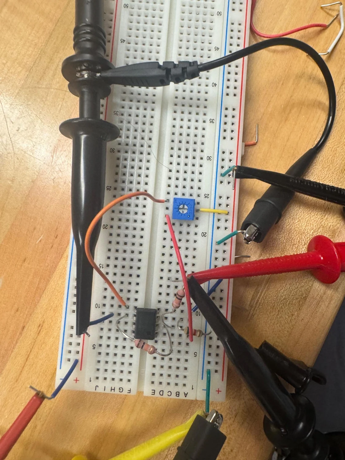
Before using the 555 to measure anything, we wired it as an oscillator. A capacitor charges and discharges between two thresholds, roughly one-third and two-thirds of the supply voltage. Each time it reaches a threshold, the chip changes state. That repeating analog voltage becomes a digital pulse train.
In this arrangement, the capacitor charges through R1 + R2 and discharges through R2. The period is approximately 0.693 × (R1 + 2R2) × C, and the fraction of the cycle spent high is (R1 + R2) / (R1 + 2R2). Changing R2 therefore changes both frequency and duty cycle. Increasing it slows the oscillator and brings the duty cycle closer to 50%; decreasing it makes the output faster and proportionally longer on. That relationship belongs to this circuit, rather than being a general rule about frequency.
Making one second
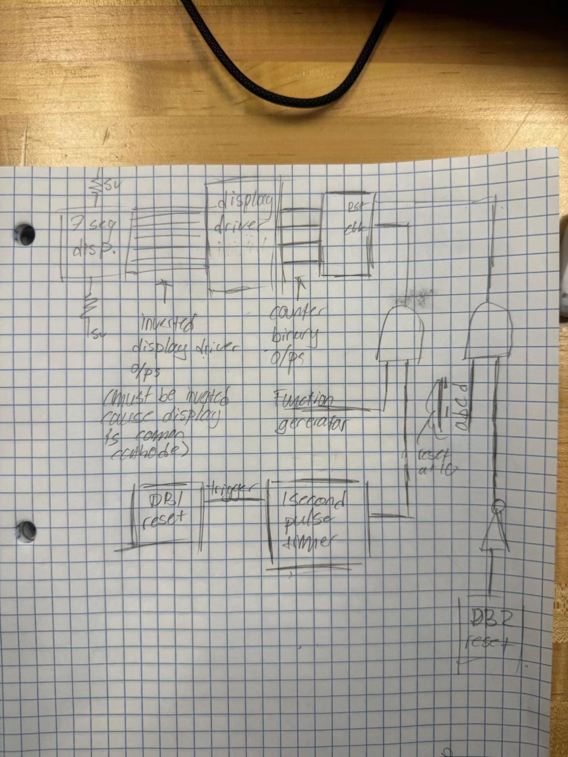
For the counter, we needed one pulse after a button press instead of a continuous oscillation. In this one-shot configuration, the trigger lets a discharged capacitor begin charging. The output stays high until the capacitor reaches two-thirds of the supply, then returns low and discharges the capacitor for the next trigger.
The pulse length is approximately 1.1RC. With 100 kΩ and 10 µF, that gives 1.1 seconds. Timing our recorded output gave 1.07 seconds: close to one second, but long enough to matter when that pulse is the measurement window.
Turning time into a count
An AND function passes the incoming square wave only while the timer output is high. The counter counts rising edges, and the display turns its binary output into a readable digit. We made the AND function from a NAND gate followed by an inverter because those were the parts we had.
The reset input was active low, meaning zero requests a reset. Combining two normally high reset conditions with an AND gate lets either one pull reset low. That allowed a manual reset and the rollover logic to share the same input. With one decimal digit, the display only represents counts from 0 through 9 before wrapping.

The extra count
We kept getting a reading one higher than expected. Looking at the input and timer together on the scope showed that the gate stayed open long enough to admit another edge. Replacing the 100 kΩ timing resistance with 90 kΩ brought the nominal pulse to 0.99 seconds and gave the expected readings in our tests.
The broader relationship is count ≈ frequency × gate time. A slightly shorter pulse helped this build, but it is not a universal calibration method: component tolerances and where the window falls relative to an input edge still matter. This was a small counter for learning how timing and logic fit together, with the scope helping explain what the display alone could not.